The screen GUI changes according to the selected layer.
The GIS waterworks and sewerage layer appears as shown in 2.1.
The Epanet ayer appears to look like 2.2.
The SWMM layer appears to look like 2.3.
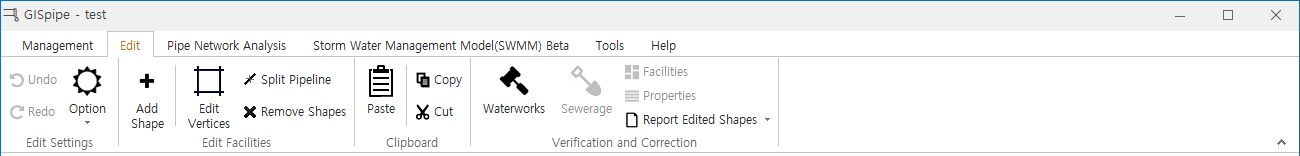
2.1 The GIS Waterworks And Sewerage Layer Editing
Add Shape : Simply select the layer on which you want to add a shape, press the Add Shape button, and add the shape to the map. For a line or polygon, click today's mouse button to finish. If you press the ESC key while adding, the drawing is cancelled.
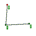
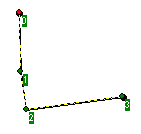
Edit Vertices : If you click the Edit BUTTRESS button and select a shape to edit on the map, it will change to a dotted line as shown in the figure below.
You can change the shape by moving the green dot.
Clicking the green dot removes the clicked vertex and clicking between the solid lines adds the vertex.
Split Pipe: A function to divide a pipe.
Move Shapes : Drag and drop the selected shape to move it.
Remove Shapes : This function removes selected shapes.
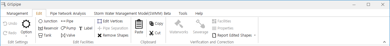
2.2 EPANET Layer Editing
Pipe : A function to add pipe.
If a pipe is open on the map screen, it is displayed as shown below.
If a pipe is closed on the map screen, it is displayed as shown below.
Pump : A function to add pump.
If a pump is open on the map screen, it is displayed as shown below.
If a pump is closed on the map screen, it is displayed as shown below.
Valve : A function to add valve.
If a valve is open on the map screen, it is displayed as shown below.
If a valve is closed on the map screen, it is displayed as shown below.
Junction : The ability to add junction.
Reservoir : The ability to add reservoir.
Tank : The ability to add tank.
Edit Vertices : The ability to edit a green dot as shown in the figure below. You can change the shape by moving the green dot. Clicking the green dot removes the clicked vertex and clicking between the solid lines adds the vertex.
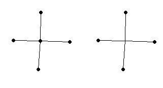
Pipe Separation : As shown in the figure below, the first picture shows the pipe before splitting and the second picture after separating. Click the edge point in the fill diagram and click the pipe separation box to detach the pipe.
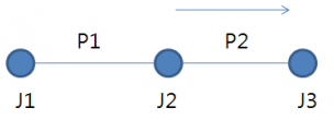
Junction removal function
Select the J2 junction in the figure below.
When you drag a J2 node to J3 point, J2 node is deleted P2 link and P1 link is connected with J3 node.
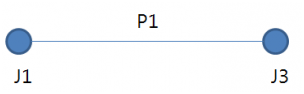
The J2 node is deleted as shown in the figure below.
Node merge function
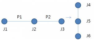
Select the J3 node in the figure below.
Dragging and dropping the J3 node to the J5 node deletes the J3 node and links the P2 link to the J5 node.
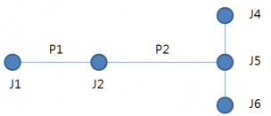
Connect as shown below.
2.3 SWMM Layer Editing
3 Clipboard
A function to select, copy, and paste shapes.
Copied figures can also be pasted into the same layer and pasted into another layer.
It is also compatible with EPANET layer and GIS facility layer.
4 Verification And Correction
4.1 Waterworks
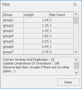
If you click the pipe correction button, the connection of the pipe is checked internally, then the pipe is automatically corrected and the calibration result and the pipe network group are displayed like the upper window.
Double-clicking on a group will move it to the location of the channel group on the map.
4.2 Report Edited Shapes
Correction and editing can be confirmed by table or ShapeFile export.